Temperature Controlled, Vacuum Encased,
PROPELLANT MIXER![]()
Temperature Controlled, Vacuum Encased,
PROPELLANT MIXER![]()
![]() Introduction
Introduction
During the course of solid propellant research and small scale motor production, the need for reproducible mixing is always encountered. Besides homogenous mixing action, it is also often necessary to:
![]() Heat the mixed
mass to reduce the viscosity and thus enable higher solids loading;
Heat the mixed
mass to reduce the viscosity and thus enable higher solids loading;
![]() Remove the air
trapped by the mixing action, in order to ensure a reproducible propellant
burn rate, as well as to approach the theoretical propellant density, and
thus volume and ballistic properties.
Remove the air
trapped by the mixing action, in order to ensure a reproducible propellant
burn rate, as well as to approach the theoretical propellant density, and
thus volume and ballistic properties.
These actions are commonly performed by commercial motor manufacturers, but are usually not done by amateurs. The common amateur practice involves mixing the propellant, either manually or using a mixer, adding the curative, and then outgassing the resulting mixture in a vacuum. Since the propellant mixture is usually very viscous, the vacuum requirements are rather high. Even so, it is nearly impossible to efficiently remove all the air trapped by the mixing action, mainly due to high viscosity and due to outgassing time limitation, brought about by usually short propellant pot life. To overcome these limitations, and to enhance air removal, amateurs have devised numerous techniques, usually consisting of mechanical agitation of propellant under vacuum conditions. This approach has been proven to be only partially successful, and the propellant quality has been shown to be operator dependant.
Therefore, the need exists to improve the mixing/outgassing process,
while placing it within the realm of amateur practice. To achieve this,
I decided to take a page out of professionals' book, and to adopt it to
amateur needs.
![]() Heater
Construction
Heater
Construction
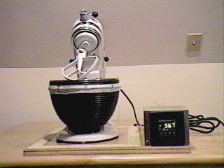
For a mixer, I chose KitchenAid kitchen mixer. Although somewhat
costly (US$200+), it is already used by many serious amateurs, and is powerful
enough to deal with most viscous of the propellants. It is also capable
of prolonged operation, and slow, powerful mixing action.
KichenAid mixer comes equipped with a stainless steel bowl, thus making
it a good candidate for propellant heating. This is achieved by means of
25 foot, rubber enclosed, heating cord, commonly available from most hardware
stores. This cord is normally used for heating water pipes during the winter,
and is rather inexpensive. Invest in a new cord, rather than making do
with something old, of questionable quality and thus safety!
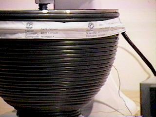
Starting at the bottom, the cord is tightly wound around the outside
of the bowl, tacking it in places with RTV or similar adhesive. Only a
single layer is applied, and a few extra feet are used as extra supply
cord. Under no circumstances is the cord to be cut or otherwise damaged.
To ensure cord stability, a single turn of paper adhesive tape is applied
near the top of the bowl. It is important that this tape not be made of
plastic, since it will stretch under elevated heat conditions.
![]() Temperature
Control
Temperature
Control
The propellant temperature is monitored by means of a J-type thermocouple, in intimate contact with the bowl, and secured under the heating coil. Do not use RTV in this area!
Temperature is controlled by means of a process controller. This controller monitors the sensor temperature and turns on the power as required to maintain the set point. Nowadays, one has many options in selecting the controller. I have chosen the CN9112 process controller available from Omega Engineering, Inc.(1-800-826-6342), for around US$200. This controller offers some very advanced options (PDI etc.), most of which I have forgone for the sake of simplicity. It is line operated, features digital temperature display, and comes with instructions detailing its operation, uses and programing. One safety feature I liked in particular, is its ability to determine sensor failure, and thus prevent overheating. It also offers programs for a range of sensors, although J-type thermocouple is probably the most effective.
I implemented the simplest of control alogaritms offered, an �On-Off', or so called �bang-bang' control. The set temperature is reached within minutes, and is maintained with +-0.5 degrees accuracy. If you do not like degrees Centigrade, it will also show degrees F.
If outgassing option is not needed, this is all that is necessary to construct a temperature controlled mixer. However, with little extra effort, it is possible to construct simple, yet very effective, vacuum encased mixer. In addition to well mixed and outgassed propellant, this option will offer longer effective pot time, since the post curative vacuuming is eliminated.
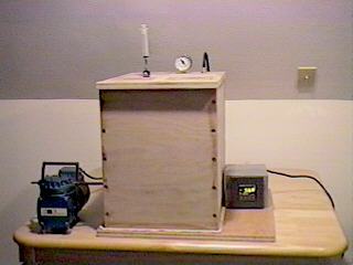 The
vacuum enclosure is constructed of 3/4" wood paneling (yes, wood).
It is necessary to use a strong composite, such as oak, since at -25 in.
Hg, the atmosphere exibits a force of over one tonn upon each of the enclosure
sides.
The
vacuum enclosure is constructed of 3/4" wood paneling (yes, wood).
It is necessary to use a strong composite, such as oak, since at -25 in.
Hg, the atmosphere exibits a force of over one tonn upon each of the enclosure
sides.
The enclosure is made just big enough to house the mixer. It consists of two parts: the bottom plate, and the top enclosure. The paneling needs to be free from warping, cut accurately and straight, so unless you have necessary tools to do this, you might want to have your hardware store do the cutting for you. In most cases, they will be happy to help you, for a couple of additional dollars. This is well worth it!
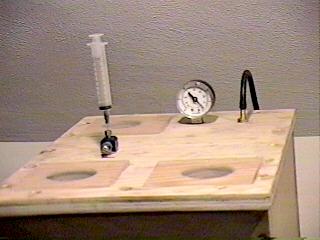
The top enclosure is constructed on a flat surface, the sides being assembled first. In order to minimize air leaks, it is important that the bottom of the enclosure be aligned on a flat surface. The sides are assembled using five wood screws per joint. To ensure airtight fit, liberal beads of RTV are applied to all joints and the screw holes. The top plate is assembled in a similar fashion. A couple of two inch holes are also provided on the top plate, along with ports for vacuum pump fitting and for the pressure gauge.
The inside of the enclosure is entirely coated with RTV, including the insides of 2' port holes, in order to enhance air tightness. Finally, acrylic or similar material windows are affixed, and sealed with RTV. The enclosure should be allowed few days to dry completely.
The bottom plate is treated with acrylic spray, urethane or other wood sealer, and allowed to dry.
 As
a final step, gaskets are applied to both the bottom plate as well as to
the bottom portion of the enclosure. I used 1/16 inch Kevlar sheet because
it was handy, but it can be made of whole range of elastomers available
to the builder. It is important that each gasket be cut as a single piece,
with no breaks in it. Nominally, the gaskets will have identical dimensions,
overlapping the sides by about 3/4 in.. They are fixed to their respective
members with liberal application of RTV. Before the RTV sets, a thin layer
of Vaseline or silicone grease is applied to both gaskets. The enclosure
is then placed on the bottom plate, and the vacuum pump is engaged. As
soon as the vacuum starts to build, the atmospheric pressure will cause
the top enclosure to apply pressure, and a portion of RTV will be squeezed
out from under the gaskets. It is important to apply only limited vacuum
at this time (about 5in Hg); too much vacuum will deform the gaskets. The
correct pressure can be gauged by observing RTV. Finally, the fixture is
allowed to cure fully. This will take few days.
As
a final step, gaskets are applied to both the bottom plate as well as to
the bottom portion of the enclosure. I used 1/16 inch Kevlar sheet because
it was handy, but it can be made of whole range of elastomers available
to the builder. It is important that each gasket be cut as a single piece,
with no breaks in it. Nominally, the gaskets will have identical dimensions,
overlapping the sides by about 3/4 in.. They are fixed to their respective
members with liberal application of RTV. Before the RTV sets, a thin layer
of Vaseline or silicone grease is applied to both gaskets. The enclosure
is then placed on the bottom plate, and the vacuum pump is engaged. As
soon as the vacuum starts to build, the atmospheric pressure will cause
the top enclosure to apply pressure, and a portion of RTV will be squeezed
out from under the gaskets. It is important to apply only limited vacuum
at this time (about 5in Hg); too much vacuum will deform the gaskets. The
correct pressure can be gauged by observing RTV. Finally, the fixture is
allowed to cure fully. This will take few days.
It is not necessary to provide any additional hardware to secure the top enclosure to the bottom plate. The atmospheric pressure will provide force of about 1500 lbs., uniformly distributed on the gaskets. The user only needs to insure clean seal (no dirt etc.), and a fresh layer of the grease.
Under the vacuum conditions, some bowing of the larger sides is evident. The amount will depend on the materials used, as well as on the exact dimensions of the enclosure. Since the engaged gasket area is large, this will usually present no problem. If the seal is compromised due to bowing, it is possible to limit the flexure by means of strategically placed stops, attached to the bottom plate and aligned with the inside wall centers. I have not found this to be necessary in my setup.
Once ready, the enclosure should be repeatedly tested under the highest attainable vacuum for prolonged periods (1-2 hours min.). This should be done before the mixer is integrated into the setup. Any structural failure would result in an inward cave-in, thus severely damaging any enclosed equipment. If the propellant was being mixed at the time, serious safety issues would also arise. So test, test, test, and be safe.
All the cables from the mixer and the temperature controller are conducted through the holes on the bottom plate, and are also sealed with RTV. Several arrangements are possible, so I will leave it to the skill of the builder to implement the most suitable approach.
One feature evident on the enclosure is the addition of curative injection system. The curative is injected under vacuum conditions, from a pre-filled syringe, mounted on the top plate. The syringe is connected to the airtight fitting affixed onto a small Teflon valve assembly. The other side of the valve protrudes into the enclosure, and is attached to small diameter (32/1000" ID) Teflon tubing. This tubing is strategically positioned above the bowl, as to dispense the curative into the propellant mixture. Prior to use, the air is eliminated from the valve and the tubing by completely flushing it with the curative from the syringe. The valve is kept closed until the curative is dispensed.
This procedure outlines the very basic framework of the propellant manufacture, and by no means constitutes the entire propellant manufacturing method nor does it depict all of the safety procedures. Thorough familiarity with manufacturing of propellants and safety procedures is assumed. This information is offered for education purposes only, and it should not be construed as encouragement or inducement to propellant or other flammable or explosive substance manufacturing.
The propellant manufacturing process is performed as outlined below:
![]() The bowl is brought
to the set temperature (I use 55C).
The bowl is brought
to the set temperature (I use 55C).
![]() The binder is
added to the bowl. The viscosity reduction will be evident with the increased
temperature.
The binder is
added to the bowl. The viscosity reduction will be evident with the increased
temperature.
![]() Plasticizer is
added and mixed with the binder until a uniform mixture is achieved. If
HX878 bonding agent is used, it is usually premixed with the plasticizer.
Plasticizer is
added and mixed with the binder until a uniform mixture is achieved. If
HX878 bonding agent is used, it is usually premixed with the plasticizer.
![]() Metallic fuel
and catalysts are added as appropriate. They are manually
mixed in with the binder mixture until the uniform mixture is attained.
Metallic fuel
and catalysts are added as appropriate. They are manually
mixed in with the binder mixture until the uniform mixture is attained.
![]() The oxidizer is
added at this time. The mixer is kept running at slow speed, while the
oxidizer is slowly added. Adding the oxidizer too fast will make the whole
process more difficult, so take your time.
The oxidizer is
added at this time. The mixer is kept running at slow speed, while the
oxidizer is slowly added. Adding the oxidizer too fast will make the whole
process more difficult, so take your time.
![]() When the mixing
process is complete, all the power is turned off, and the enclosure is
placed over the mixer. The vacuum pump is engaged, and the pressure is
monitored until the minimum is achieved.
When the mixing
process is complete, all the power is turned off, and the enclosure is
placed over the mixer. The vacuum pump is engaged, and the pressure is
monitored until the minimum is achieved.
![]() The temperature
controller is then turned on. It will take ten or so minutes until the
mixture reaches the set temperature. At this point the mixer is re-engaged
by turning the power on. While mixing in a vacuum, the air bubbles will
be evacuated very efficiently. This process will not take very long, but
I usually do it for 30 minutes.
The temperature
controller is then turned on. It will take ten or so minutes until the
mixture reaches the set temperature. At this point the mixer is re-engaged
by turning the power on. While mixing in a vacuum, the air bubbles will
be evacuated very efficiently. This process will not take very long, but
I usually do it for 30 minutes.
![]() At this point
the propellant is ready for curative injection. Depending on curative used,
reducing the bowl temperature may be necessary as to enhance the propellant
pot life.
At this point
the propellant is ready for curative injection. Depending on curative used,
reducing the bowl temperature may be necessary as to enhance the propellant
pot life.
![]() As a final step,
the curative is added by opening the Teflon valve. Injecting the curative
manually is not necessary, since it will be drawn in by the vacuum. The
calculated volume of the curative is thus dispensed into the bowl. The
syringe graduations will greatly aid in this process.
As a final step,
the curative is added by opening the Teflon valve. Injecting the curative
manually is not necessary, since it will be drawn in by the vacuum. The
calculated volume of the curative is thus dispensed into the bowl. The
syringe graduations will greatly aid in this process.
![]() The mixing operation
is continued for a couple of minutes, until a homogeneous mixture is achieved,
and the enclosure pressure is then slowly released. No further outgassing
is required.
The mixing operation
is continued for a couple of minutes, until a homogeneous mixture is achieved,
and the enclosure pressure is then slowly released. No further outgassing
is required.
Propellant is now ready for use, with only couple minutes of pot time consumed. This allows the use of faster, room temperature, curatives such as Isonate 143L.
![]() Results
Results
I routinely achieve 25 in. Hg vacuum, in this setup, using the pump
as shown. Upon microscopic examination, I could not find any air inclusions
in propellant that has been processed in this manner. Also, the propellant
density is the within experimental measurement error of that theoretically
predicted. I could not achieve this performance with the best (10um) pump
available, while using the usual outgassing methods.
![]()
![]()
If you have any comments or questions regarding this article, e-mail
me!
Last update on 04-Sep-96 - Copyright © 1996 Chris Krstanovic (WR1F)