![]()
![]()
The Static Test Stand (STS) was designed to aid in propellant development,
as well as for static motor testing. It has proven to be very flexible
and with addition of appropriate accessories, it was utilized for a wide
variety of applications ranging from ignition research to thrust vector
control experiments. STS is comprised of three sets of subsystems:
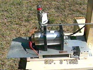
1. Test Bed
 This
is the business end of the setup. It consists of a test plate mounted on two
pairs of high precision linear bearings. To achieve low limiting friction, the
bearings were very accurately aligned. The test plate was designed to carry
a wide range of accessories, thus facilitating versatility in experiment design.
This
is the business end of the setup. It consists of a test plate mounted on two
pairs of high precision linear bearings. To achieve low limiting friction, the
bearings were very accurately aligned. The test plate was designed to carry
a wide range of accessories, thus facilitating versatility in experiment design.
The thrust is measured by means of Omega load cell mounted behind the plate. The load cell is rated to 70 lbs force, with less than 0.5% of non-linearity and hysteresis (combined). During the calibration it seemed to outperform the specifications, at least short term. To date, testing performed indicates ability to cope from 'A' size motors to over 50 lbs thrust. The main chassis was built from 0.75" 6061-T6 aluminum. In places, it is reinforced with 1.5" aluminum machined parts. This was necessary in order to minimize flexing, since this has negative impact on linear bearings and thus on overall accuracy.
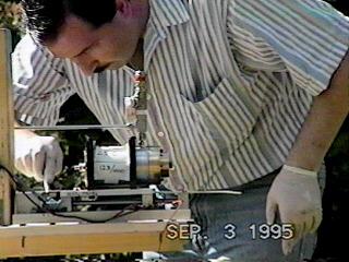
The test bed can be mounted for vertical use, but the preferred
method is a horizontal mounting because of its insensitivity to depleting
propellant weight.
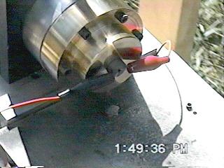
2. Accessories
 In
addition to various motor mounts and holders, a fixture was designed mainly
for the purpose of propellant and material testing under realistic rocket combustion
chamber conditions.
In
addition to various motor mounts and holders, a fixture was designed mainly
for the purpose of propellant and material testing under realistic rocket combustion
chamber conditions.
The fixture is essentially a housing for a 2" PVC pipe, which is used as a shell containing a propellant load. In this manner, a wide variety of experiments can be carried out very rapidly, ranging from grain testing to propellant parameter evaluations. Typically it is possible to reload the housing within 5 to 10 minutes. PVC was chosen for its availability, low thermal conductivity and exceptionally high heat of fusion. Its mechanical properties are not important since it is not exposed to any significant stress. The PVC is usually fitted with EPDM rubber liner to enhance propellant adhesion and prevent uncontrolled 'under-burning'. This is particularly important for end burners (constant burn rate testing).
The housing consists of 6061-T6 Al cored bar, with brass fittings on either end. One of the fittings is designed to accept readily and quickly interchangeable, 1" graphite nozzle. The nozzle is of a tapered design, containing two disposable O-rings. This guarantees a good seal with increasing chamber pressure.
 The
design burst pressure is >12,000 psi with 2X safety margin. The end plates
are designed so that the screws will fail at 3400 psi. This was done to further
enhance safety by providing for a controlled pressure release. The end plates
are sealed using Kevlar(tm) gaskets. They are rated to >1500psi.
The
design burst pressure is >12,000 psi with 2X safety margin. The end plates
are designed so that the screws will fail at 3400 psi. This was done to further
enhance safety by providing for a controlled pressure release. The end plates
are sealed using Kevlar(tm) gaskets. They are rated to >1500psi.
Two 1/4" pipe ports are provided for monitoring chamber pressure. One is located radially, close to the nozzle and is used during end-burner tests; the other is mounted axially, on the rear end plate. The provision is made for a pressure relief valve as added safety feature. Industrial grade pressure sensor (0-5000 psi) terminates 24 inch long, 0.25"seamless stainless steel tubing, emanating from pressure monitoring ports.
3. Data Acquisition and Remote Control System
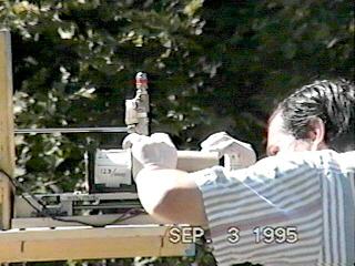
The inherent hazards of propellant testing dictates the necessity to isolate the operator from the test site. To this end, a microcontroller system was designed containing 8 channel, 12 bit A/D converter, as well as all the necessary control and power electronics. All the inputs were equipped with isolation and instrumentation amplifiers to further aid in test flexibility.
The system was designed to work in tandem with a personal computer acting as a main controller, data logger, and providing user friendly interface. The communications between the systems are carried by bi-directional fiber optic cables. The control point is usually 150 feet away from the test site.
The PC control software was written in Quick Basic. In addition to data logging, translation, and system control, the software has partial control over the remote fire control system. For that reason there are two safety keys; one is hardware and the other is in software. It was necessary to do this due to potential (and likely) human error in systems of increased capability and complexity. This is further reinforced by the fact that, in a setup such as this, many tests can be carried out in a rapid succession.
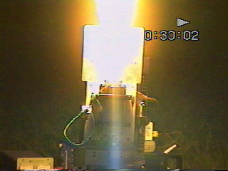
Test Burns
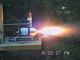

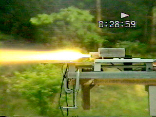

Test Data Samples
Chamber Pressure:
Thrust (lbf)
This work was performed by the author, Chris Krstanovic, in 1995.The
above charts are copyrighted and may NOT be reproduced without prior consent
from the author.
For comments, suggestions or questions ![]() ,
Chris Krstanovic.
,
Chris Krstanovic.
Last update on 22-Aug-96 - Copyright © 1996
Chris Krstanovic (WR1F)